
VEX Robots can be more competitive when they have addressed several drive motor control challenges:
- Stopping a motor completely when the joystick is released. Joysticks often do not output a value of “zero” when released, which can cause motors to continue turning slowly instead of stopping.
- Starting to move gradually, not suddenly, after being stopped. When a robot is carrying game objects more than 12 inches or so above the playing field, a sudden start can cause the robot to tip over.
- Having motor speeds be less sensitive to small joystick movements at slow speeds. Divers seeking to position the robot precisely during competition need “finer” control over slow motor speeds than fast motor speeds.
These challenges can be solved using one or more “if” statements in the code controlling the robot, however using a single polynomial function can often solve all of these challenges in one step. A graph can help illustrate the challenges and their solution:
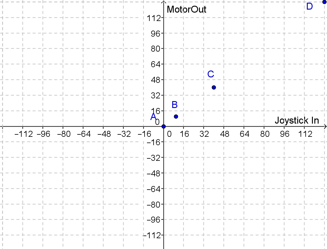
The blue points in the graph correspond to the most common way that motors are controlled by a joystick: the same value received from the joystick is used to set motor speed. A line connecting the blue points would have the following equation:

Its slope is 1, and its vertical axis intercept is zero, so the blue line in the graph below gives us a visual description of the complete motor control algorithm:

While this approach is certainly the easiest to think about and implement, once you have taken Algebra II it does not take much time or effort to dream up an improved motor control algorithm. If we plot the MotorOut values we would prefer to use for each JoystickIn value, points A and D might remain as they are above, but we might prefer the green points BModified and CModified instead of points B and C for the following reasons.
If the joystick is released but does not recover into the exact center position, it will probably produce an input value within 10 or 15 of zero. The green point BModified on the graph would have this situation produce a MotorOut value of 1, which is not likely to be enough power to turn a drive motor, so the motor would stop even though the joystick might not have returned to the exact center. This would address the first challenge described at the start of this post.
The two remaining challenges described at the beginning are both addressed by the point CModified. When the joystick is moved a small distance away from its center position, the JoystickIn value is likely to be greater than the ideal drive motor output value for slow movement. If this input value can be reduced somewhat before being sent to the drive motor, say from a value of 40 to something closer to 10, that will allow for more gradual drive motor starts as well as more precise turns (less risk of over-correcting the robot’s direction). And, more gradual motor starts will help reduce the risk of having the robot tip over when it has game objects lifted to a high position.
So, what kind of an equation would pass through the perfect stop (0 , 0) and full power (128 , 128) points, but get from one to the other in a more gradual way? If you trace a rough curve through points A, BModified, CModified, and D, do you recognize that shape, or at least something close to it?
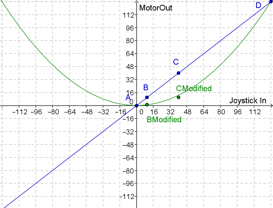
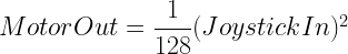
The green curve above does not quite pass exactly through the two green points, but it is pretty close. More importantly, it does pass through (0, 0) and (128, 128), ensuring you can instruct the motors to produce both maximum and minimum power. The shape of the green curve is a parabola, which tells us that we can model it using a second degree polynomial equation: a quadratic equation.
Since we know the desired vertex is (0, 0), we can start with vertex form of a parabola, then substitute (0, 0) in for the x and y coordinates of the vertex:

This equation is guaranteed to pass through the vertex (0, 0), but we now need to find a value for “a” that will force the equation to also pass through (128, 128). We can do this by substituting the x and y coordinates of this point into our equation above, then solving for “a”:

So, the equation of the green curve in the graph above is
If you use this equation in your drive motor control task, you will hopefully discover that it produces much smoother starts, and more reliable stops. However, as the graph above indicates, it also causes a problem: the robot will not move backwards, as the curve only produces positive MotorOut values.
One way to fix this is to use a “piece-wise” function which dilates the left half of the parabola vertically by a factor of negative one (rotating it about the horizontal axis), while leaving the right half untouched:
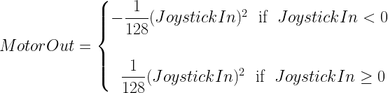
Conditional logic can implement this easily in your drive motor control task:
if (JoystickIn < 0)
MotorOut = -(JoystickIn^2) / 128
else
MotorOut = (JoystickIn^2) / 128;
Another way of coding this is:
MotorOut = (JoystickIn^2) / 128;
if (JoystickIn < 0) MotorOut = -MotorOut;
Another approach would be to try a mathematical solution to the problem, by choosing a polynomial with an odd degree (an odd highest power of x), which will allow the function to produce negative as well as positive values. So, starting with a cubic function that is symmetrical about the origin and only crosses the x axis at the origin, we get:
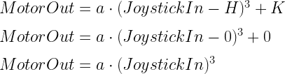
Then solving for the value of “a” that will force this curve to pass through (128, 128):

The graph of this equation is the tan curve on the graph below, along with our previous two equations:

And this motor control algorithm could be implemented in your drive motor task with even less code:
MotorOut = (JoystickIn^3) / (128^2);
However, note that cubic function (tan) grows more slowly for small values of JoystickIn than the quadratic (green), so it is possible that your driver(s) may prefer one approach over the other, particularly when trying to position a robot precisely in front of an object. So, give them an opportunity to try each, then keep the winner. Alternatively, you could put them both into your code, with the choice of drive algorithm chosen by whether a button on the controller is held down at the moment, or not:
if (Button6)
{
MotorOut = (JoystickIn^2) / 128;
if (JoystickIn < 0) MotorOut = -MotorOut
}
else
{
MotorOut = (JoystickIn^3) / (128^2)
};
When automating tasks, it is often useful to think carefully about whether controller inputs should be passed on as outputs unchanged, or whether safety, reliability, and/or overall performance might be improved by having the output be something different than the current input value. Thinking this through can often be a bit easier and more complete if you use a graph, as was done above. If you decide that it will be useful to have the output differ from the input, is that difference something that can be described easily by a mathematical function? Your graph should help you answer that question quickly.
Another example of where outputs may need to differ from inputs arises if you wish to prevent motor speeds from changing too rapidly, thereby preventing “jerky” robot movements. Any significant changes in input values would need to be “tempered” by the software in a way that still feels responsive, but nevertheless enforces some limit on how fast motor speeds are allowed to change. A mathematical function could take the current and desired motor speeds as inputs, and provide the maximum new motor speed as an output. The following implementation of this idea allows only 30% of the desired change to happen each time the current joystick position is read (each time through the drive motor task loop):
MotorOut = MotorNow + (JoystickIn – MotorNow) * 0.30
So, if the current motor speed (MotorNow) is 20, and JoystickIn is calling for a speed of 100, the first time your drive motor task has a chance to respond to this new joystick position, it would set MotorOut to

The next time through the drive task loop, if JoystickIn is still 100, MotorOut would be set to

The next time through the drive task loop, if JoystickIn is still 100, MotorOut would be set to

As you can see, the motor speed will gradually approach 100, with a “smoother” change in speed from the initial speed of 20. However, the approach to the desired motor speed could end up still being too fast (it will not take more than a second to get above 95), so you should play around with the 30% number to determine whether some other number (perhaps between 0.1% and 30%) works better for your robot.
Risks to using this approach include the slower acceleration that this creates, as well as the possibility that full power might not be able to be reached quickly enough. However, using this approach alongside the approach described above can help produce a “feel” that your drivers might prefer.
So, think about your control algorithms. Try having outputs be a mathematical distortion of the inputs, then decide on what seems to work best for your robot design and driver(s) preferences. Your robot and team will benefit from your experimentation!

